Brock Environmental Center: Virginia Beach, Va.
Strong Through the Storm
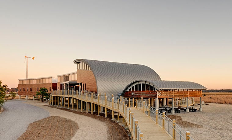
For buildings to withstand sea-level rise, coastline erosion, and hurricanes, they need to be built to work with nature, not against it. The Brock Environmental Center is a living example of how to minimize impact on the environment while being resilient to future challenges. The triple net zero building is the latest to receive Living Building Challenge certification and is the first in the U.S. to receive a permit for drinking rainwater treated to federal standards."
The nation’s largest nonprofit regional environmental organization, the Chesapeake Bay Foundation (CBF), is dedicated to restoring the health of Chesapeake Bay by advocating and litigating for effective regulations, conducting hands-on habitat restoration projects, and educating the general public about the Bay and solutions to restore it. CBF has also led by example, creating pioneering models for green design, such as its headquarters, the Philip Merrill Environmental Center.
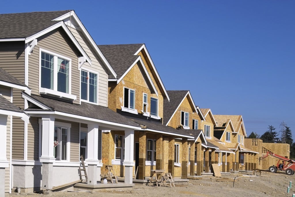
The Brock Environmental Center was the result of a community effort to save a 118-acre parcel from planned development including over 1,100 new high-rise condos and townhouses. A partnership between CBF, the City of Virginia Beach, and the Trust for Public Land preserved the land for open space and environmental education. The 10,500 ft2 Brock Environmental Center houses staff offices, meeting rooms, and an 80-seat conference room.
With the goal of creating a model for sustainable design, the building team aimed for the most advanced of all sustainable building certifications, the Living Building Challenge. Certification requires net zero energy, net zero water, and net zero waste.
Integrated Design Strategies
Brock’s design was shaped by the net zero energy goal, taking advantage of passive measures and then meeting the resulting demand using high performance equipment and controls. The team embraced a highly iterative, integrative process using simulation tools to validate each design move.
Siting Brock’s coastal site was once an intertidal marsh, providing valuable habitat for plant and animal life. The shoreline of the site consists of naturally occurring wetlands, while former marshes filled with spoils from a 1970s dredging project are experiencing ecological succession into vibrant salt meadows. The Center was sited to minimize impact to the landscape, clustering development along the edge of the successional maritime forest. Siting also anticipated the onset of sea-level rise and storm surges that occasionally flood the site.
The design team considered the current shoreline and the projected shoreline in 2100, when the sea level is expected to have risen by 3 ft. The building is set back 200 ft from the shore and sits on pylons 14 ft above sea level.
Envelope Design The Center’s one-story, long and narrow footprint oriented on an east-west axis maximizes opportunities for daylighting and natural ventilation. It curves slightly to the east, allowing morning sun to preheat the interior office before occupants are typically present.
The exterior envelope was optimized (R-31 walls, R-50 roof, R-7 triple-glazed/argon-filled windows) to reduce heating demand. To minimize cooling loads, windows were placed and sized to provide optimal daylight, views, and ventilation, without excessive heat gain from over-glazing.

Photo by David Chance
Natural ventilation is used, even though the building is located in a place that typically doesn’t pursue it because of the hot, humid summers and cold winters.
Natural Ventilation The wind rose for the project site indicated a strong NW and SE split that varied seasonally. The project is located in ASHRAE climate zone 4A, a location that typically doesn’t pursue natural ventilation solutions because of the hot, humid summers and cold winters. Building owners and designers also tend to associate risks with operable windows such as security, pollen, noise, air infiltration, controls challenges and added costs.
Design temperature and humidity for natural ventilation mode were established at dry-bulb temperatures between 45°F and 78°F and an outdoor air absolute humidity below 88 grains per pound.
Lower casement windows are designed to promote catching the wind, given the slight angle of the wind direction. The upper awning windows are designed to maximize the open area and provide some protection from the elements.
The team selected a combination of cross and stack ventilation strategies (Figure 1) to provide flexibility. Many natural ventilation hours, particularly during the warmer seasons, occur overnight when the office is closed.
 A night flush system that opens the upper windows through the building controls system automatically precools the building down to 68°F. This design extends the occupied time before mechanical cooling is required. Modeling predicted that natural ventilation can effectively cool the building loads for over 11% of the occupied hours of the year.
Daylighting Extensive daylight modeling helped optimize daylight levels while reducing direct sunlight penetration. Strategies such as reducing south-facing glazing, optimizing visual transmittance of the glazing, and using a south-facing exterior porch all minimized glare. North-facing windows and clerestories maximize diffuse daylight from the north (Figure 2).
 Operational Strategies Daily operational schedules were created for each space, including conference and group areas often used by visitors. While challenging, the exercise helped determine how much energy each event would consume and better predict ventilation and cooling needs. In turn, it proved key to predicting building energy use and correctly sizing renewable power systems.
Mechanical
A geothermal piping loop provides the heat sink for the building ventilation, cooling and heating loads of the building. The load profiles and ground temperatures allowed the design to use water only and avoid glycol.
The LBC permits the use of high-density polyethylene for the ground loop piping. The vertical well loop minimizes site disturbance and consists of 18 closed loop, geothermal bores that are 250 ft deep.
Outside air is provided to the building using a 1,400 cfm water-cooled dedicated outside air system (DOAS), which provides the required ventilation air as specified by ASHRAE Standard 62.1-2007.The DOAS unit is connected to the geothermal loop and ducted directly to all rooms in the building. Demand controlled ventilation using CO2 sensors serve all group spaces to minimize outside air during periods of low occupancy.
A total energy recovery wheel pretreats the outside air using building relief air and then repurposes the relief air for composter toilet exhaust makeup air. Exhaust is required for the composting toilets and is required to be run continuously to promote the composting process within the tanks.
The design team evaluated a water source heat pump and a water-cooled variable refrigerant flow system tied into the geothermal loop. The team analyzed energy use, and considered other factors such as first cost, acoustics, space needs, flexibility and controls.
The VRF system provided 5% energy savings annually compared to the WSHP system. The design team also felt the VRF system improved flexibility within the open spaces while not negatively impacting acoustics.
After visiting an installation of a VRF system with the owner, the geothermal VRF system was selected. The system includes three 7-ton water-cooled condensing units piped in parallel and connected to 18 indoor VRF units.
The condensing units each have a two-way control valve to control the water flow through the units, and digital scroll compressors to match the building load precisely. The indoor VRF units vary by space type, suiting the architectural design of the room they serve. The system is a thee-pipe, heat recovery type to allow for load sharing and thermal zoning.

Daylight modeling resulted in consistent, diffuse daylight in the open office, eliminating need for electric lighting during the day.
Lighting and Controls The team designed a number of active strategies that resulted in a lighting system that consumes 5% of the lighting energy typically used in an office building (CBECS 2003). Lighting calculations were coordinated with furniture locations to ensure appropriate lighting levels.
Photosensor dimming allows most spaces to function using solely daylight. Time clock and occupancy settings further reduce energy use.
Another focus was minimizing plug load consumption, which started with selecting Energy Star-rated equipment. The building’s control system includes plug-load controls to reduce or even eliminate “vampire loads.” Almost all receptacles in the building are turned off after-hours when the building is unoccupied.
Water In the pursuit of net zero water, rainfall data was collected and used to identify a typical drought period. Two standing seam metal roofs capture rainwater, filling two 1,650-gallon cisterns, enough to withstand five to six weeks of drought.
Ozone is injected into the cisterns to keep the tanks clean. The system consists of a booster pump, treatment skid, and pressure storage tanks located in a building loft. Rainwater is treated on demand whenever the system fills the pressure tank. The treatment skid consists of four-log cartridge filters and ultraviolet disinfection. The Center was the first in the U.S. to receive a commercial permit for drinking treated rainwater in accordance with federal requirements. Composting toilets reduce water demand while also treating waste on site. Solid compost is used on site, while leachate is stored, sent to a local struvite reactor and converted into fertilizer. Rain gardens treat graywater and filter excess roof runoff, managing all storm water on site.
Renewables Two 10 kW wind turbines bookend the Center on the east and west ends of the building. The height of the turbine poles (70 ft) and location of the turbines were selected to minimize turbulence from nearby trees and minimally disturb the environmentally sensitive site.
For wind turbines to be feasible on a given site, a fairly steady wind speed is needed; an average annual wind speed of at least 12 mph is typically recommended. This building site just met this recommendation.
The power output of the two turbines is individually metered, which has assisted in troubleshooting. The output of the 45 kW PV system is also metered, which has allowed the design team to compare predicted versus actual output of both systems.
As a grid-tied system, this surplus energy is returned to the grid for use by other consumers. Early on, the team compared the predicted output of the wind and PV systems and also studied the relative cost of each system.
This led us to develop a $/kWh metric that compared the cost versus production for the wind and PV systems. (The cost was distributed across an assumed 25-year service life for each system.) These values are site specific since both the production and the installed cost of each will vary between different sites. We found that the PV system had a cost of $0.20/kWh while the wind turbine system had a cost of $0.38/kWh.
This indicates that for our project site, the PV system was a more cost-effective means of producing electricity. However, our team and our client were interested in proceeding with a wind turbine system for a portion of the electricity production both as a test case for wind turbines and as a way of diversifying the source of renewable power for the building.
A Different Approach for Life-Cycle Cost Assessment
Living Building Challenge (LBC)/Net zero energy goals altered our approach to life-cycle cost assessment (LCCA). The cost benefit of conservation approaches was measured against the cost of on-site renewables, rather than against the cost of cheap, grid-provided electricity. This approach put an increased emphasis on conservation.
The investment in insulation, triple-pane windows, ground-source wells, etc.. was cost effective given their ability to reduce the demand for photovoltaics. An LCCA was used to validate HVAC system selection comparing the VRF system used against a more conventional ground-source heat pump. The energy savings from the VRF system eliminated the need for $15,000 of additional photovoltaics.
Some strategies, like rainwater harvesting, didn’t prove to have economic justification, but rather were adopted to catalyze change within the building and regulatory spheres. LBC material requirements often limited competition, escalating project costs. Approaches that could not be economically justified had to be justified for their potential to impact greater ecological awareness. Excluding sitework costs and the premium to elevate the building above the flood plain, Brock’s construction costs were just over $400/ft2 (including on-site renewables).
 Performance
On April 1, 2015, the Chesapeake Bay Foundation turned off the municipal water and began operating the Brock Environmental Center using only collected rainwater. Concurrently, the team began monitoring daily energy consumption and production, comparing actual data to modeled predictions. Since then, the renewables have generated 82.7% more electricity than the building has consumed, and Brock achieved full Living Building Challenge certification in May 2016 (Figure 3). •
About the Authors
Brian Coffield, P.E., is a mechanical engineer and principal with SmithGroupJJR. Sara Lappano, P.E., is an electrical engineer and principal with SmithGroupJJR. Greg Mella, FAIA, is an architect and vice president with SmithGroupJJR, as well as the co-director of sustainability for the firm.