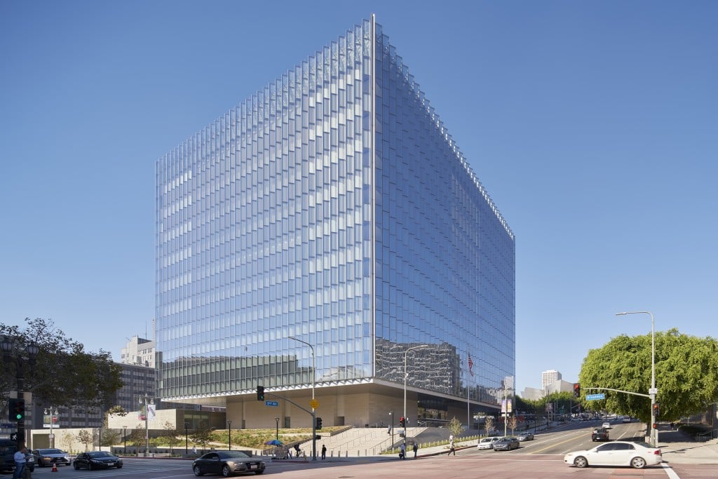
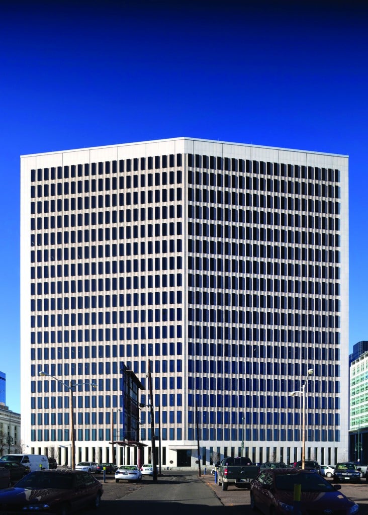
Byron G. Rogers Federal Building: Denver, Colo.
From Retro to Retrofit
Modernizing Denver’s 1960s-era Byron G. Rogers Federal Building capitalized on a decision made in 1850 by the original city planners to lay out the downtown streets at 45 degrees to the four cardinal points. Without considering the solar orientation, the Byron Rogers complex design respected the street orientation and the result placed the main buildings facing southwest and the hot afternoon sun. While this is great for watching the sun set over the mountains, the building becomes a giant solar heat collector.
When it came time to renovate the building, one of the design-build team’s major goals was to reduce the building’s energy use to below 30 kBtu/ft2·year (which was more aggressive than the General Services Administration’s project requirement to be lower than 39.1 kBtu/ft2·year). The challenge was how to achieve these aggressive energy targets with this old, poorly sited building. Rather than fight the building, the team changed its perspective and thought about how it could use the original attributes to its benefit.
Because the southwest elevation was an unintended solar heat collector, the team pushed forward the idea to “capture” the unwanted heat, store it and then move the heat around the building to areas that needed it using a 50,000 gallon thermal storage tank, magnetic-bearing chillers, and chilled beams.
Balancing Act
This project was a balancing act of multiple, sometimes competing, goals and expectations and necessitated an integrated team that brought creativity, longevity and confidence to the final solutions:
- Preserve the historic design and provide a contemporary interior design in harmony with the building’s original architecture. Built in 1965, the building remains an emblem of its time, and is a noteworthy piece of federal architecture in Denver (see sidebar Modern Architecture: A Stellar Example).
- Upgrade the existing envelope to support aggressive energy reduction goals, improve occupant comfort, and reduce stack effect.
- Provide significant safety improvement, invisibly, for progressive collapse, blast protection and seismic upgrades.
- Set the building on a path to achieve GSA’s 2030 energy goals.
Project Scope
A nearly total gut of the building’s interior (including complete asbestos abatement) only left historically significant interior design elements, the primary structure, and the historic exterior envelope. These bones served as the framework on how to best rethink, design, and operate the high-rise building in the future.
 |
|
Guided by the GSA's First Impressions Initiative, the design improved the appearance and efficiency of the public spaces, articulated the entrance area and alleviated security-check queuing delays. |
|
© Raul Garcia |
A major focus was to reorganize the core building functions into a more efficient and flexible arrangement. The team focused on the user’s experience to simplify wayfinding while creating a memorable experience. The design of the central core and primary circulation paths provides: unobstructed views to the exterior; equally obvious men's and women’s toilet locations (relocated from the ends of the building); a consolidated, symmetrical core maximizing efficient and flexible tenant layouts for single or multi-tenant floors; and the “race track” circulation path on each floor. The interior design includes forms and finishes that reinforce wayfinding around each floor and limit the need for signage.
Mechanical and electrical rooms were moved to building ends to free up room within the central core and better serve the different zones of the building. A centralized phone and data distribution network was stacked to provide efficient flexibility for changing tenants. The project required structural seismic upgrades, and interior columns were carefully organized in the ceilings around the central core to support seismic needs and to create a zone of heavy floor loading for tenants.
Floor-by-floor main distribution pathways (ducts, hydronic pipes, and conduit) were organized above the racetrack circulation hallway. These lower ceilings reinforce the main circulation path, celebrate the “fish” shape of the building, and provide flexibility for multi-tenant floors. Higher ceilings were achieved at the perimeter, which allowed natural daylight to penetrate further into the building and into enclosed internal offices.
Envelope and Windows
Solving the building envelope issues required a highly integrated team. The envelope system had to address several factors: maintain the historic building design, keep the existing precast in place, accurately match window frame profiles and details, provide glass tint that is historically accurate yet reduces heat gain and maximizes daylight admittance, install blast windows and supporting structure, install progressive collapse structure, achieve an effective R-9 exterior wall (total of all window and opaque walls), and maintain vapor barrier continuity around existing structural elements.
The most prominent historic design element of the building is the pattern of slender aluminum windows and carefully articulated polished aggregate precast concrete panels. The tall windows on the upper floors project out past the face of the precast panels, while at the lower floors the windows are recessed deeply into the building plane. The precast is irreplaceable and known to be brittle when handled; therefore, it was decided to keep the existing precast panels in place and perform all work from the building interior. This also avoided scaffolding 18 stories or performing work from a swing stage.
The upper floors’ 1,500 dark bronze windows project 4 inches out from the precast panels. While architecturally critical to the building design, the solution was a nightmare for energy efficiency because the aluminum frames act much like fins on a radiator that effectively transfer heat in and out of the building. However, changing the projection was forbidden.
Fortunately, the frames were generally in good shape and could remain if alternative solutions were developed to reduce heat loss and address blast requirements. The frame manufacturer studied ways to recreate a new and better projected window frame that limited the “radiator” effect and could resist blast loads. Unfortunately, it was not possible.
The team developed another option: to keep the existing frame in place, and then install a new blast window on the interior. This proved to be the most viable option because it also increased the thermal performance of the window system and facilitated an easier installation and fabrication of blast structural steel and window. It was determined that an operable glazing unit on the interior side of the existing frame would provide an insulating chamber between layers of glass, could accommodate breather tubes to prevent heat buildup, and would allow for routine maintenance at the inside faces of the window chamber. Careful engineering and modeling software studied how solar orientation and temperature/relative humidity differentials affected the cavity.
Ultimately, everyone contributed to the solution by fine-tuning each piece of the assembly: the building’s relative humidity was controlled more accurately, the tint color performance was fine-tuned, the type and face of low-e coatings were adjusted to allow more heat from the building interior, the thickness of blast film adjusted, and vent holes to the exterior were added to relieve pressure.
The precast panels are supported by a secondary structure that is held off the primary structure/slab edge by a few inches. The secondary structure vastly complicated solutions to insulate the wall, separate floor-to-floor air atmospheres, and maintain continuity of the air/vapor barrier. The final solution placed mineral wool directly against the back of the precast, which was then covered with spray foam insulation that functions as the thermal, air, and vapor barriers. A 15-minute thermal (think fire) barrier was added to allow the spray foam to be exposed to the ceiling plenum space. Vapor barrier transition membranes were designed where materials changed. Cementitious fireproofing was studied to determine its vapor permeance and maintain continuity of the vapor barrier. Through this process, the team reduced the thickness of the exterior wall assembly, increasing leasable area.
The window and opaque wall upgrades were a success. The solution was invisible from the outside (and ostensibly from the inside, too), protected occupants from a bomb blast and progressive collapse, and achieved superior thermal performance with an effective wall value of R-9 (effective R-3.7 windows and R-20 opaque walls). In addition, through the integrated team approach, several steps were simplified to reduce construction time and increase quality.

| Emerging Technologies | |||
|
From the outset, an overarching goal was to deliver a project that sets the standard for public and private sector office renovation projects alike. Active chilled beams, heat pump chillers, thermal storage, and 100% LED lighting were determined to be viable design strategies for future General Services Administration (GSA) office renovation projects, in part, through their successful performance on this project. In addition, the Byron Rogers project informed the GSA’s then-new Green Proving Ground (GPG) program, which leverages GSA’s real estate portfolio to test innovative building technologies and to accelerate the transition between bench-scale technology and commercial viability. Changes to GSA’s design standards have also been informed by the emerging technologies successfully used on the Byron Rogers project. Also, due to its age and condition, the building was selected to receive funding for a complete remodel through the 2009 American Reinvestment and Recovery Act (ARRA). Because the GSA received additional ARRA funding strictly to incorporate emerging energy-efficiency technologies such as LED lighting into the design, the GSA established aggressive sustainability targets well beyond federal requirements for the project. |
Lighting
A key challenge to the project was procuring American-made fixtures to meet the GSA requirements of using 100% LED lighting throughout the tower. At the time of the design, domestic production of LED fixtures was in its infancy, and there simply were not enough manufacturers with the capability or capacity to adequately serve the needs of the project (see sidebar Emerging Technologies).
To circumvent this, GSA and the design-build team worked closely with manufacturers to help them develop solutions to meet design criteria, while making certain concessions that enabled lamp and fixture production to ramp up to meet quality specifications.
An ambitious project goal was to light the entire building with LEDs at 0.55 W/ft2. Achieving this goal was complicated because “standard” office-type LED fixtures where not commercially available at the time. To address this issue, the team conducted a design competition to compare custom-designed LED fixture prototypes from different manufacturers. A workable LED fixture was selected for the project, and a majority of the custom-designed prototypes ultimately went into full-scale production.
 |
|
Reorganization of the building core, coupled with active chilled beam and LED lighting, supported the design for exemplary environments including open office areas along the exterior, allowing daylight to penetrate deep into the floor plate. |
|
© Raul Garcia |
Light fixtures within 15 ft of the building perimeter have daylight sensors. These fixtures were originally programmed not to provide any light if a sufficient amount of daylight entered a given space. On average, the lights were turned off approximately 40% of the time on the southwest façade and 20% of the time on the northeast façade. After occupancy, a tenant survey was done, in part, to evaluate the performance and user satisfaction of the lighting controls. Based on the results, it was determined that more light was needed in the perimeter zones for a combination of reasons (e.g., height and width of the windows, configurations of columns and pilasters, desk location within the office). The lighting was reprogrammed so the lowest light output level during occupied hours would be 20% of the light source’s maximum output level. Reprogramming the lighting was relatively easy due to the adjustable nature of LED fixtures, and the reprogramming had a very minimal impact on energy savings or ROI.
HVAC Systems
One building façade faces northeast while the other building façade faces southwest, making one side of the building much warmer than the other.
Therefore, the design team applied a whole-systems approach featuring heat reclamation, chilled beams, and a thermal storage system that transfers heat from the warmer side of the building to the cooler side and vice versa. A chilled beam system primarily uses moderate temperature water (an extremely efficient heating/cooling medium) to condition building spaces. After capturing heat generated in the building by occupants, computers, lighting and solar gain, a hybrid magnetic bearing heat recovery chiller and a 50,000-gallon thermal storage tank were designed to circulate stored heat through the building’s chilled beam system as needed. The tank was sized to accommodate the heating and cooling needs overnight and weekends by only operating pumps and avoiding operating energy-consuming chillers and boilers during unoccupied hours.
 |
|
Magnetic bearing chillers. |
|
© Raul Garcia |
The building is ventilated via two dedicated outdoor air system (DOAS) units located in the penthouse. These units are dual tunnel and contain a heat recovery wheel that draws the heat out of the restroom exhaust. The DOAS system serves the floor level blower coils, which mix ventilation air and return air on the floors. This air is circulated to the active chilled beams, which provide heating and cooling via a system similar to a two-pipe changeover for each of the three exposure zones on the floor.
Before the building automation program was implemented, the design-build team tested the program without controlling any devices. The desired condition parameters were set, and the team observed how the program reacted to those parameters. If certain components did not respond as intended, adjustments were made to reconfigure the system. Also, the design-build contractor and subcontractors conducted training sessions of all building systems for the building management staff. These training sessions were video-recorded for future reference. “Refresher courses” were conducted several months after occupancy to familiarize existing and new O&M staff. During the second round of training, manufacturer representatives and subcontractors assisted O&M staff with issue resolution. These step-by-step tutorials help O&M staff diagnose and troubleshoot common issues.
A chilled beam system uses water pipes that require significantly less space than conditioned air ducts, allowing for greater floor-to-ceiling heights throughout the building. With the greater ceiling heights and removal of the induction units, 30% more window area was created for daylight and views. For spaces with private offices on the perimeter, the design-build team encouraged tenants to install translucent or transparent side lights to provide more light into the interior spaces. •
About the Authors
Matthew C. Bartels, AIA, is a principal with BWG Architects. Michelle L. Swanson, P.E., LEED BD+C, is a senior mechanical project manager from The RMH Group.