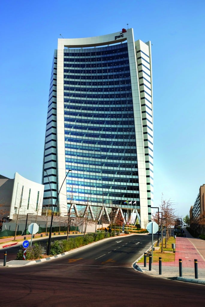
PricewaterhouseCoopers (PwC) Headquarters, Johannesburg, South Africa,

A high-rise tower that gently twists with 30 degrees of rotation between the ground and top floors also keeps South Africa’s environmental challenges of water scarcity and limited electricity supply in mind. The new energy-efficient air-conditioning system is based on a low water and electricity consumption four-pipe chilled and hot water system. Using new state-of-the-art water-cooled chillers and three new multifunction four-pipe units, the carbon footprint of the building is substantially reduced compared to most other buildings in the area.
The developer and tenant were very clear on the overall design brief: The new PricewaterhouseCoopers (PwC) headquarters in Johannesburg, South Africa, had to be an iconic building, unique to the development, and had to establish the property as a new top tier destination for business. It also had to conform to the internationally recognized LEED BD+C v3.0 (2009)1 silver rating criteria. On completion, this 516,667 ft2 (48,000 m2) building boasted 25 levels of prime office space and meeting rooms, and an adjacent annex building with sound studios, training rooms, large commercial kitchens, a staff canteen, forensic rooms, computer rooms, archive rooms, triple volume entrance foyer as well as a structured parking basement. A future trigeneration plant2 could easily be accommodated and integrated into the current HVAC system.
This article outlines the HVAC design approach that was followed and includes the thermal zoning strategy, fresh air supply strategy as well as equipment selection. The incorporation of various advanced technologies in the field of air-conditioning in combination with the innovative designs of the architect, façade engineer, mechanical engineer and the other professionals delivered a world-class, energy-efficient building.
Design Approach
The air conditioning for this building was designed to meet the following criteria: commercially economical, high operational efficiency, excellent occupant comfort, good thermal zoning, simple and easy to maintain, simple to operate, good service access to all HVAC equipment, relative high fresh air rates to occupants, good system reliability, long service lifespan, high filtration efficiency, integrated heating and cooling recovery, high performance glazing, automated internal blinds system, extensive carbon monoxide (CO) and carbon dioxide (CO2) control and advanced controls.
During the initial stages of the project, various chiller technologies were researched to enable the delivery of the best solution that complied with the client brief. During the detail design stages, various sun studies and energy modeling were done to assist the designers in delivering excellent occupant comfort.
System Description
The air-conditioning system comprises a central cooling and heating four-pipe system. Chilled water is generated on site by a combination of two state-of-the-art high efficiency water-cooled screw chillers, plus three multifunctional four-pipe air-cooled units. Hot water is generated on site by means of the three multifunctional four-pipe units. These five chillers work in combination to provide the best energy efficiency, lowest water consumption and lowest energy cost, all depending on the cooling demand, the ambient temperature conditions and the electrical time of use tariff.
 |
|
Various stages of construction are evident. The core in the center, followed by the floor plates, followed by the façade. |
|
Photo: P.J. De Bod |
The chilled water is pumped by means of constant primary and variable secondary pumps3 to various fan coil units (FCUs), air-handling units (AHUs) and computer room air-handling units (CRAHs) in insulated steel piping. Chilled and hot water are supplied at a temperature of 46.4°F (8.0°C) and 95°F (35°C), respectively, to FCUs or AHUs that can cool or heat the internal space to meet design conditions.
Thermal Zoning Strategy
To ensure the occupants are comfortable, the correct thermal zoning was of utmost importance. The typical shape of the tower floor plates is in principle a triangle, but the three straight sides are concave. In addition to this, the tower floor plates rotate 1.2 degrees clockwise every floor, so that the top floor and the ground floor are rotated 30 degrees clockwise.
Perimeter Zone
The collective effect of the concave shape and floor rotation resulted in multiple thermal zones per floor, each to be controlled carefully to ensure best occupant comfort. Following a long design review process, it was decided to install various FCUs in the ceiling of the perimeter zone of 12 ft (3.65 m) deep, each with individual temperature control, for the following main reasons:
- Optimal zone control: Compared to a central variable air volume AHU system, FCUs provides superior independent zone control for each zone along this building’s façade, keeping in mind that the façade direction varies at each level as the building twists upward, and each office level of the façade faces three different directions.
- Excellent flexibility: It is easier to deal with tenant changes on a FCU compared to a central AHU system. To change, add, and remove FCUs to accommodate major office churn is straightforward. The FCU can serve a meeting room, executive office or canteen, without affecting the surrounding air-conditioning zone or systems.
- Future proofing: Chilled and hot water piping is provided in the ceiling with additional pipe stubs with isolating valves for future FCUs.
Each FCU contains the necessary washable removable filters, insulation, cooling and heating coil and three-speed supply air fans. In most cases return air is drawn into the ceiling voids and mixed with a regulated amount of filtered outdoor air.
Internal Zone
The internal zone of the “triangle” floor plate is served by means of a variable air volume air-handling unit with variable flow diffusers. Each floor is served by its own AHU.
No electrical heating is installed anywhere in the HVAC system, as this is very inefficient and environmentally unfriendly.
The internal design temperature for the office area is 72.5°F (22.5°C) in summer and 70.7°F (21.5°C) in winter. These are the temperatures at which the majority of people are considered comfortable, and they are accepted as standard indoor design conditions in South Africa. The occupant comfort modeling that was done has proved the same result of good occupant comfort.
Outdoor Air Supply Strategy
The requirement of high fresh air rates was also considered to be a very important design aspect of the HVAC system. In the tower building, two dedicated outside AHUs are located on the roof of the tower, providing treated fresh air to all the FCUs in the perimeter zone. Air is supplied at a neutral temperature of 64.4°F (18°C). Provision is made to fit rotating heat recovery wheels in the future to the dedicated outside AHUs. The riser ducting for the central toilet extract system for the tower is linked to a backward-curved centrifugal fan that is located close to the dedicated outside AHUs, which is ideal for heat recovery. The toilet extract air is exhausted to the atmosphere at high velocity.
 |
|
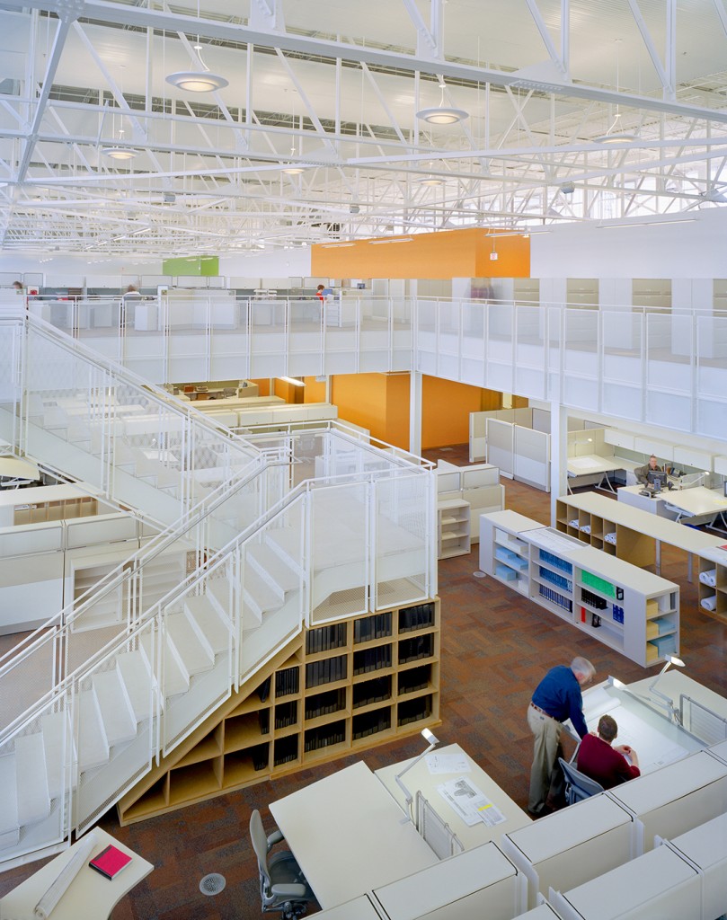
The air-conditioning, heating and ventilation system is carefully integrated in the interior outfit. This photo illustrates an integrated black variable air volume diffuser, and a wall thermostat on the left. |
The variable air volume air-handling units on each typical tower floor draw in fresh air and mix it with return air before supply into the internal space. Each AHU is linked with a CO2 meter to constantly monitor and control the fresh air. The same design approach was followed for the rooms in the training workshops, staff canteen and circulation areas.
All the AHUs are capable of performing a nighttime flushing cycle and an economy cycle, both to conserve energy. During the summer, the nighttime flushing cycle supplies outdoor air to the office space, typically in the early hours of the morning. The objective is to remove the inertia heat buildup (heat that is present in the slab and other materials in the building), thereby reducing the cooling demand at start-up the next day, saving energy.
Water-Cooled Chillers
The heart of the cooling system is the two ultraefficient water-cooled chillers, each producing 300 tons (1055 kW) of cooling. Each water-cooled chiller is piped to a dedicated closed-circuit cooling tower (with VFD on the fans) to cool the condenser water. The chiller provides high energy efficiency using a variable speed, positive displacement screw compressor. The chiller has the ability to reduce speed and optimize operation independent of ambient conditions.
The chiller has a very low harmonic distortion effect4 due to an integrated VFD that provides a soft start, further reducing stress on the compressor and inrush current at start-up.
The chiller can precisely match building load and conserve energy for high part-load performance. (Table 1 indicates the high part-load conditions that contribute to the low energy cost in providing chilled water.)

Multifunctional 4-Pipe Chilled And Hot Water Generators
The heat recovery multifunctional four-pipe unit is mainly sized to meeting the space heat demand for the building. Each chiller can operate in three different modes: heating only, cooling only, and simultaneous cooling and heating.5 The maximum efficiency of the chillers is reached with simultaneous loads, during opposite overlapping thermal loads. Other benefits of these four-pipe units include the chiller plant areas that are reduced, hydronic circuits that are simplified and maintenance that is reduced by half.
Using traditional ratings such as EER and COP to measure efficiency of four-pipe units would be limiting, but to objectively measure performance under simultaneous load conditions, the rating total efficiency ratio (TER) is used. The TER is calculated as the ratio between the sum of the delivered heating and cooling power and electrical power input.
 |
|
The central cooling plant is located on ground floor level to enable easy access to the large cooling equipment and pumps. Special acoustic cladding is installed on the walls of the plant room to dampen the noise from the mechanical equipment. |
|
Photo: P.J. De Bod |
In part cool, part heat mode, all the evaporating and condensing energy is used for the system, and only requires part of the total energy, and in this particular state, the exchangers are “oversized,” achieving an even higher efficiency.
The multifunction four-pipe unit is sized based on ambient summer condition 95.0°F (35°C) dry bulb and ambient winter condition 32.0°F (0°C).
Automated Internal Blinds
This building is equipped with a sophisticated automated blind system linked to numerous solar sensors located on the external façade of the building. Appropriate sun studies revealed that the same façade can have sun and shade, a result of the concave triangle design and rotating floor levels. A few minutes before the sun’s rays hit the glass façade, the blinds will close. This system automatically opens and closes blinds on various sectors of the façades depending on the angle of the sun and the time of the day. This system is incorporated to control glare and minimize solar influx into the building. Two different types of blinds were used: perforated roller blinds (for the office floors in the tower) and horizontal venetian blinds with a drop down function and auto tilting function.
Reception Desk and Cast In Slab Heating
Johannesburg, South Africa experiences cold, dry winters, and the comfort of receptionists in the foyer is ensured by designing and installing an innovative heating system integrated into their desks. An uninsulated hot water pipe is located in the foot well of the desk. Receptionists may want to rest their feet on the hot water pipe to provide heating during cold days. Each receptionist desk has its own heater and thermostat. Low pressure hot water circulates through the pipes. The hot water system is hydraulically separated from the main building’s hot water system by means of a plate heat exchanger. A small circulation pump circulates hot water to the reception desk heating and in slab underfloor system.
Underfloor hot water heating is also installed in the main lobby in the ground floor slab. This heating system is designed to combat the cooling effect of the large single glazed glass in the lobby area, to make the space more comfortable for occupants.
Energy and Environmental Impact Monitoring System
The purpose of the environmental impact monitoring system (EMS) is to display, monitor and record the electrical and domestic water consumption and to make the occupants aware of the environmental impact that the building and its systems have on the planet. Further functionality of the EMS is to create and distribute custom-made reports and graphics, which assist in understanding and managing the energy and consumption pattern of the large electrical and water consumption components.
Basement Extract System
Most of the car parking is in an underground basement. The entire parking basement is mechanically ventilated with large axial fans connected to the smoke detection system and a CO sensor system.6 The same system doubles as a fire smoke extraction system in line with the fire engineers rational fire design. The operation of the axial fans is controlled by the CO monitoring system. If the CO levels are less than a predetermined value, the fans switch off, and will start and ramp up based on the detected CO levels. In case of a smoke or fire alarm, all the fans on the level will switch on.
 |
|
Construction of the inner core and basements began in the first quarter of 2015. Practical completion was early in 2018. |
|
Photo: WBHO |
Kitchen Ventilation
The staff canteen is capable of providing meals for up to 4,000 employees. Stainless steel canopy hoods with ultraviolet lights and a small air jet are installed in heavy cooking areas in the commercial kitchens to break down grease.
Most of the grease exhausted from the hood can be classified as fatty acids, which consist of long chains of molecules connected by double bonds, which are chemically reactive. One of the chemical reactions that occurs is called photolysis and takes place when UV light7 hits the long molecular chains and breaks the double bonds. Ozonolysis also takes place, which is facilitated by ozone generated to react with the smaller chains of grease and grease vapors to chemically alter them. The resulting substance reduces the particles that stick to the ductwork or fans, which lowers the fire risk. Low noise, high pressure backward-curved fans are located on the roof of the canteen building and extract the canopy smoke. A fire suppression system is also installed in the canopies.
The smoke-capturing air jet decreases the airflow, while increasing the smoke capturing efficiency and reducing the fan energy consumption. This minimizes the heat and impurities produced by cooking appliances that spread to the work area. Compared to conventional exhaust-only hoods, this hood is claimed to be up to 23% more efficient.
 |
| The high-rise tower gently twists with 30 degrees of rotation between the ground and top floors. |
|
Photo: Johann Duvenhage |
Building Automation System
The building is equipped with a new building automation system (BAS). The BAS is a localized computer-based monitoring system that monitors the building’s HVAC system, generators, UPS, main electrical meters, main water meters, and fire detection system alarms. All the information is transmitted to a central computer in the control room on level 1 where it is displayed in graphical format. The information on the BAS can also be assessed remotely and can be set to trend and store data for troubleshooting purposes.
The BAS is also used for alarm management. Critical alarms are sent via text messages to the facility manager. Water and electricity consumption are also tracked and the information used for reporting purposes. The BAS network uses a dedicated LAN cable and is separate from the PwC network.
Pressure independent control valves (PICVs) have been installed in all the chilled and hot water supplies to FCUs, AHUs and CRAHs to automatically compensate for chilled and hot water pressure variations. This enables continual balancing functions to maintain system performance at varying loads, and to prevent cooling and heating at the same time. These PICVs maximize the energy savings of variable flow pumping systems.
Stair and Elevator Pressurization
The elevator shafts and fire escape staircases in the tower are pressurized by means of axial fans located on the roof of the tower. To ensure that temperatures do not build up in the tower staircases, a motorized fire damper on each floor has been installed at ceiling level connected to a thermostat. The damper will open when the temperature in the staircase exceeds 77.0°F (25.0°C) allowing secondary air from the office space to flush the staircase. This was tested during the commissioning phase and proved to be very effective.
24-Hour Computer Room System Cooling
A dedicated chilled cooling system provides cooling to the server room, MDF rooms and other similar rooms. Either FCUs or CRAHs are connected to the chilled water system to ensure these rooms are cooled without interruption. A separate air-cooled chiller provides the cooling, but in case the chiller fails, an automatic changeover is made to the central cooling system. On the basis that the cooling demand is not higher than 30 tons (105 kW), it was decided to design a dedicated system to avoid running the main chilled water plant continuously after-hours.
Building Flushing
To comply with the minimum requirements of the Indoor Environmental Quality section of the LEED rating system, the building has been flushed in accordance with the LEED requirement Path 1, which is to flush the building after construction, prior to occupancy, with all interior finishes installed, with new filter media, supplying a total air volume of 14,000 ft3/ft2 (4267 m3/m2) of outdoor air while maintaining an internal temperature of at least 60°F (15°C) and a relative humidity less than 60%.
This equated to a total of 6,356 million ft3 (180 million m3) of outdoor air, equivalent to 72,000 Olympic-sized swimming pools. This was done over a period of between 10 and 21 days, using the 34 air-handling units and accompanying fresh air fans. The purpose of the flushing is to evacuate airborne contaminants.
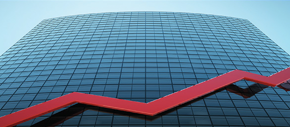
Glazing Selection and Solar Reflectance of Concave Façades
The glazing selection for this building was one of the most important design elements. The glass that was selected was a toughenable double silver coating with high solar protection and superb light and energy performance. This tinted gray glass has low interior and exterior light reflection, and its coating can withstand the toughening process. The angles of the solar reflection on the uniquely warped concave shape of the façade of the PwC building was carefully modeled up-front to prevent any high levels of solar reflections on the ground and neighboring buildings.8 Concentration contours on the ground have been modeled by the façade engineers.
 |
|
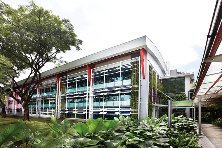
The building’s uniquely warped concave shape of the façade varies at each level as the building twists. This tinted gray glass has low interior and exterior light reflection. |
The modeling process revealed that the initial solar concentrations were up to 0.55 kW/ft2 (6 kW/m2) in some places, which is about six times stronger than normal. The spandrel panels were acid-etched glass with the outside surface acid etched to create a nonreflective surface. This resulted in a reduction of the reflective area by roughly a third. The sun’s rays are also dispersed before hitting the ground because the glass is not perfectly flat. The final solar concentrations were slightly more than 0.18 kW/ft2 (2 kW/m2), and it was agreed to hard and soft landscape the surrounding areas. The team considered installing pipes in the affected areas to heat up water, but this was not viable because the amount of effective time that the pipes received solar reflectance was minimal. Examples of solar reflectance of concave buildings is the Walkie Talkie5 building in London (20 Fenchurch Street), which has been blamed for melting car parts in streets below.
Conclusion
The incorporation of various advanced technologies in the field of air conditioning in combination with the innovative designs of the architect, façade engineer, mechanical engineer and the other professionals have delivered a world-class, energy-efficient building design that has inspired and continues to inspire many young engineers and architects and provides a comfortable and pleasant new office for an international firm like PwC.
References
- LEED. 2009. LEED 2009 for New Construction and Major Renovations Rating System.
- Hernández-Santoyo, J, A. Sánchez-Cifuentes. 2003. “Trigeneration: an alternative for energy savings.” Applied Energy 76(1 – 3):219 – 227.
- Taylor, S. 2002. “Primary-only vs. primary-secondary variable flow systems.” ASHRAE Journal 44(2):25 – 29.
- Akagi, H. 2005. “Active Harmonic Filters.” Proceedings of the IEEE 93(12):2128 – 2141.
- Van Rooyen, M. 2018. “How the PWC Building became buildable.” Walls and Roofs 19.1:76 – 80.
- Krarti, M., A. Ayari. 2001. “Ventilation for enclosed parking garages.” ASHRAE Journal 43(2):52 – 57.
- Alexandrova, A. 2009. “Extract and cleaning of contaminated air in commercial kitchens: Ultraviolet technology.” Mikkeli University of Applied Sciences. Bachelor’s Thesis, Section 5.
- Porter, T. 2013. “London walkie-scorchie skyscraper cost-cutting blamed for car-melting, egg-frying reflected sunbeams.” International Business Times Sept. 6. •
About the Author
P.J. de Bod, Pr.Eng., is senior mechanical engineer in the Department of Mechanical Engineering at WSP in Dallas. He worked as technical director in the Bryanston Johannesburg, South Africa, office of WSP when the article was written.